DL06 Frequently Asked Questions
![]()
Use "Ctrl-F" to search for specific words in this FAQ.
Question:
Is there a way to detect a low battery condition in the DL-06 PLC?
Answer
Yes, use Special Relay SP43.
FAQ ID: 936
Question:
What is the accuracy of the PLC DL06 real-time clock?
Answer
It is +/- 1 minute per month.
FAQ ID: 989
Question:
Does the DL06 support Modbus protocol?
Answer
The DL06 supports Modbus RTU, not MODBUS ASCII. Port 1 can be a Modbus slave, address 1 only. Port 2 can be a master or slave with user configurable address
FAQ ID: 990
Question:
Does the DL06 work with radio communications?
Answer
Yes, on port 2 if you need handshaking.
FAQ ID: 991
Question:
Does the DL06 support peer-to-peer communications?
Answer
Yes, the DL06 does support peer-to-peer communications with the H0-ECOM100 (Ethernet) module.
FAQ ID: 992
Question:
To connect a modem with a DL06, do I need to jump RTS and CTS on the PLC side?
Answer
It is case by case. If your modem does not have RTS/CTS control, you need to jumper RTS and CTS on the PLC side. If your modem has RTS/CTS control, you may connect each signal to the modem. Usually, you would jumper RTS/CTS on the PLC side and the modem side and not be concerned about handshaking.
FAQ ID: 993
Question:
Can you print from a DL06?
Answer
Yes - ASCII out on a serial printer only
FAQ ID: 994
Question:
Will my D2-HPP work with the DL06 PLC?
Answer
Yes, but it must have V2.2 or later firmware. However, not all commands are supported.
FAQ ID: 995
Question:
Does DL06 have a 24V accessory power supply?
Answer
Yes, the AC powered DL06's have an internal power supply of 24 Volt DC, 300 mA. The current should be derated if the option modules use 24 VDC current.
FAQ ID: 996
Question:
Do any of the DL06s have Triac outputs?
Answer
Yes, the D0-06AA & D0-06DA.
FAQ ID: 997
Question:
Can the DL06 handle larger preset values than 9999 for counts?
Answer
Sure, just use UDC counters that counts up to 99999999.
FAQ ID: 998
Question:
Can I make two D0-06 slaves on a multi drop communicate to each other?
Answer
No, the data must be routed by the master. If you require peer-to-peer communications you need to use the H0-ECOM100 ethernet module.
FAQ ID: 999
Question:
How do you use the PID loops in the DL06 without an analog output?
Answer
You would have to use time proportional control and a discrete output. See the PID chapter in the DL06 User Manual
FAQ ID: 1000
Question:
Can you put an encoder on the DL06?
Answer
Yes. This is explained in Appendix E of the DL06 User Manual Your DL06 must have DC inputs for this function.
FAQ ID: 1001
Question:
What is the max. tolerable inrush for relay outpus on the DL06 AC units?
Answer
5A max at 250VAC resistive, 3A max at 250VAC inductive.
FAQ ID: 1002
Question:
What configuration software is necessary to use for DL06?
Answer
You will need DirectSoft programming software for the DL06. The latest version is PC-DSOFT6
FAQ ID: 1004
Question:
Do you offer a memory cartridge for the DL06 family?
Answer
No, we do not.
FAQ ID: 1005
Question:
Can port 1 on the DL06 be a master?
Answer
No.
FAQ ID: 1006
Question:
On the input power side of the unit, what type of fuse do I need for the AC powered DL06?
Answer
With 100 to 240 VAC, use 1 A(Fast blow).
FAQ ID: 1007
Question:
Is there a calendar and date in the DL06?
Answer
Yes. The PLC DL06 has a real time clock that contains the year, month, day of week, day of month, hour, minutes and seconds (V7766 through V7764). The precision is +/-1 minute per month.
See page 3-30 of the DL06 User Manual for the system registers.
FAQ ID: 1008
Question:
Does the DL06 have floating point math capabilities?
Answer
Yes.
FAQ ID: 1009
Question:
Is the Directnet protocol the same between the DL06 and the DL205?
Answer
Yes.
FAQ ID: 1010
Question:
Where are the Hours, Minutes & Seconds stored at using a DL06?
Answer
Hours in V7770; minutes in V7767 and seconds in V7766
See page 3-30 of the DL06 User Manual for all the date/time system registers.
FAQ ID: 1011
Question:
Can the DL06 series support 2 up counters in one of the high speed modes?
Answer
Yes, in mode 10 can support 2 single ended up counters, up to 5 KHz. For any application that requires more counters or faster counting rate, use the H0-CTRIO2
FAQ ID: 1012
Question:
Can the DL06 accept 5VDC inputs?
Answer
No. 5 Volt is lower than the DC input ON threshold. However, many TTL logic circuits can drive the inputs if they are wired as open collector (sinking) inputs. See chapter 2 of DL06 User Manual for I/O wiring guidelines.
FAQ ID: 1013
Question:
Can the LCD Display change bits and v-memories like an operator panel?
Answer
Yes. The LCD Display will allow you to change bits or v-memory words in the PLC. However, we strongly recommend that you do NOT use this unit as a replacement for an operator panel. All memory locations are available from the LCD panel and changing values in the PLC can lead to errors or unsafe functioning if the wrong values are changed. The LCD panel should be reserved for maintanence and troubleshooting purposes by authorized personnel.
FAQ ID: 1014
Question:
What is the I/O addressing of an option card.
Answer
a. First input of an optional input module starts at X100. First output of an optional output module starts at Y100.
b. D0-OPTIONS-M manual page 2-15 covers optional module IO mapping. Chapter 2
c. You can also get information under PLC/Configure IO. Look in the slot under the Address In and Address Out column for starting address.
d. Combo modules require more information found in Options manual. D0-OPTIONS-M
e. The controller may require a firmware upgrade if it is older than the option module.
FAQ ID: 1016
Question:
Does the DL06 have Ethernet capabilities?
Answer
Yes, but you will need to use the H0-ECOM100 ethernet module.
FAQ ID: 1017
Question:
Is there an RTD or thermocouple module for the DL06?
Answer
Yes; the RTD module is F0-04RTD and the thermocouple module is F0-04THM
FAQ ID: 1018
Question:
Do you have an adapter for the D2-DSCBL and EA-2CBL cable so that I can use them on port 2 of a DL06, DL250-1, or DL260 instead of on port 1?
Answer
You can use the FA-15HD adapter to connect to port 2 of a DL06, DL250-1, or DL260. The FA-15HD adapter will work with DirectSoft32 and the D2-DSCBL, or with a C-More panel, using the EA-2CBL cable.
Since port 2 is configurable on these PLCs, you must make sure the protocol and port settings match on both devices. The FA-15HD adapter can be used with the D2-DSCBL, the EA-2CBL, or the FA-CABKIT. The FA-15HD adapter can NOT be used with the DV-1000 or the D2-HPP.
FAQ ID: 1025
Question:
What is the format of the MWX/MRX exception buffer?
Answer
The instructions require 3 consecutive words.
If a Modbus slave device does not like something in a Modbus request it receives, it will respond with an exception response.
The exception response at the protocol level looks like:
- Byte 1 = Address Byte
- Byte 2 = Function Code of Request with Most Significant Bit Set
- Byte 3 = Exception Code
- Byte 4 and 5 = CRC Error Check Characters
These bytes are swapped in the MRX/MWX exception response buffer.
- V-Memory 1 High Byte = Function Code Byte
- V-Memory 1 Low Byte = Address Byte
- V-Memory 2 High Byte = One of the CRC Bytes
- V-Memory 2 Low Byte = Exception Code Bytes
- V-Memory 3 High Byte = 0
- V-Memory 3 Low Byte = Other CRC Byte
The eight exception codes defined by the Modbus protocol are:
- 01 = Illegal Function Code = This slave device does not support the requested function code
- 02 = Illegal Data Address = The requested data address is not valid for this slave device
- 03 = Illegal Data Value = One of the data values in a write request is invalid for this slave device
- 04 = Slave Device Failure = Unrecoverable error in the slave device
- 05 = Acknowledge
- 06 = Slave Device Busy
- 07 = Negative Acknowledge
- 08 = Memory Parity Error
The Exception Response format and error code information comes from this document: www.modbus.org/docs/PI_MBUS_300.pdf starting at page 93 (100 of 121).
FAQ ID: 1083
Question:
What is the screw size on the D-sub for port 2?
Answer
It is a metric M2.6 x 0.45 pitch
FAQ ID: 1112
Question:
Outputs are not turning on in an option module. What could cause this?
Answer
The first input of an optional input module starts at X100. First output of an optional output module starts at Y100.
Page 2-15 covers optional module IO mapping. D0-OPTIONS-M
You can also get information under "PLC >> Configure IO" in the programming software. Look in the slot under the Address In and Address Out column for starting address.
Combo modules require more information found in Options manual. D0-OPTIONS-M
FAQ ID: 1172
Question:
Output LED comes on but nothing happens in the field, what could be the problem?
Answer
a. Discrete outputs on a D0-06DD1 model, needs to have V+ terminal connected to 24vdc or positive voltage of DC power source.
b. Discrete outputs on a D0-06DD2 model, needs to have C0 terminal connected to 0vdc of DC power source.
FAQ ID: 1173
Question:
I added analog IO pointer method during online edits. I then wrote to changes to PLC. But my analog IO still does not work, where do I start checking?
Answer
Make sure you go to Program Mode, then back to RUN. If you do online edits while in RUN mode, the program mode you get when you WRITE program to PLC is just a Pause mode. You can verify by viewing values in system words (V700, V701, etc) to see if they hold the expected values. If they do not, they will populate with correct values when you power cycle the PLC or when you go to Program mode and then back to RUN mode.
Information on Pointer Method is found in the D0-OPTIONS-M manual for each analog module. Click here for Options Manual.
FAQ ID: 1174
Question:
Can I configure a DL06 to do high speed counting and generate high speed pulse output?
Answer
a. You can do High Speed Inputs or High Speed outputs, but not both.
b. Mode 10 allows you to configure two high speed counters, up to 7 KHz.
c. Mode 20 allows you to configure a quadrature counter, which allows counting in clockwise and counter clockwise directions (or count up or down), up to 7 KHz.
d. Mode 30 allows you to do high speed pulse outputs up to 10 KHz. It supports three profiles: trapezoidal, registration and velocity.
e. Click here for Appendix E of DL06 User Manual.
FAQ ID: 1175
Question:
I need to add more IO to my DL06, what are my options?
Answer
a. You can use available option modules, such as: discrete IO and/or analog IO, in the four available expansion slots.
b. If these are used up, it is possible to use the PLC as master to a second or multiple slave PLCs. You can use a serial or Ethernet connection and use RX/WX instructions to control the IO of other linked PLCs. This is not the preferred method to add IO.
c. The end of Chapter 4 in the DL06 user manual covers networking using Modbus RTU or DirecNet protocols. Port 2 on a DL06 supports RS-232, RS-422 and RS-485. Directnet can be used with RS-232 and RS-422. Modbus RTU can be used with the same electrical connections plus it also supports RS-485.
d. You should consider using a DL250-1 or DL260 CPU and the engineered local expansion and/or remote IO connections available to that family. Changing the ladder to that family can be as simple as changing the PLC type in the OFFLINE Setup.
FAQ ID: 1176
Question:
Can I read/write data from/to one or more DL PLC? How about to a non DL device?
Answer
1. The DL06 can use port 2 as a master using Direct Net or Modbus RTU.
2. Port 2 supports RS232, and RS422, for both DirectNet and Modbus. RS485 (2-wire)can only be used with Modbus. If you use RS422 or RS485 you can communicate with a network of devices. All devices on the network need to support the protocol the master DL06 port 2 is configured for.
3. If connecting to third party devices, you will use the Modbus RTU protocol. When doing so you will need to convert Modbus addressing to DL octal addressing. To help with this task, we have a Modbus Conversion utility available on our technical support page. Modbus Conversion Utility
4. The DL06 supports two instructions, MRX and MWX, which allow you to address the Modbus addresses directly without the need to convert to octal addressing.
5. Chapter 4 of the D0-06USER-M manual covers the communications port and networking starting on page 7. Click here for Chapter 4 of DL06 User Manual.
FAQ ID: 1177
Question:
Is it true you need to add some form of protection when using relay outputs to turn on solenoids or motor contactors?
Answer
Yes, it is true. Devices with coils, inductive loads, driven by a PLC relay output will generate a voltage spike when it is turned off. You should install some form of surge suppression, such as TVS, MOV or Diode, at the coil or as close to the coil of the solenoid (or other device) as possible.
This is covered in more detail in AN-MISC-032
FAQ ID: 1178
Question:
I just installed a new module in one of the expansion slots but I cannot see it in Configure I/O, what could cause this?
Answer
This is most likely the PLC firmware version. You will need to update it.
Koyo Support Tool and DL06 Firmware file
Install the Koyo Firmware Update Tool and follow the wizard to update the firmware in your PLC.
Once updated, check Configure I/O. The module should now be recognized by PLC.
FAQ ID: 1179
Question:
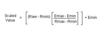
Which formula do I use to scale an analog input if my engineering unit does not start at 0?
Answer
Click here for scaling formula.
a. When using BCD or Binary data types, you will lose resolution since you cannot use the fractional values. You can multiply the engineering min and max values by a factor of 10 or 100 to accommodate for this to a certain extent. For example, if your engineering range is 0 to 100, use 0 to 10000.
b. If you are dealing with negative values in DirectLogic PLCs, it will be easier if you use floating point data type.
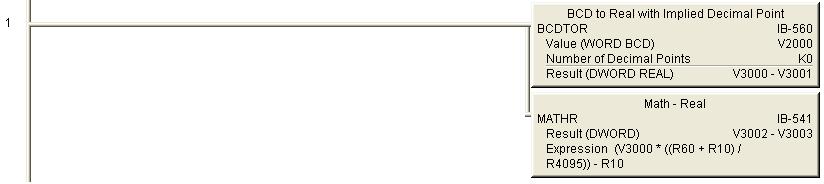
c. Ladder example using IBOX to scale -10 deg C to 60 deg C, where V2000 is the raw count (0 to 4095):
Click here for scaling example using IBOXs.
FAQ ID: 1182
Question:
How do I get the absolute value of a 2s complement negative number so that I can use it as a REAL value?
Answer
a. It is not possible to convert a 2s complement negative number directly to a REAL value.
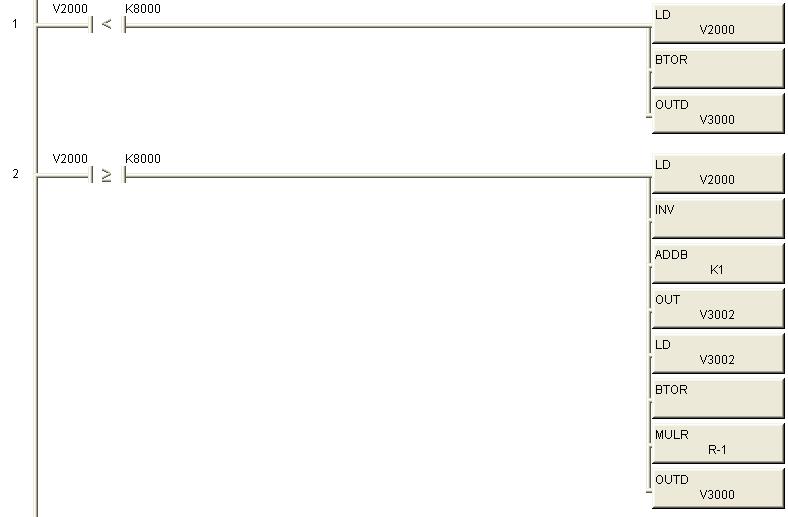
b. Example 1 below uses V2000 as the 2s complement data source and V3000 as our converted REAL value destination.
i. When a 2s complement value is negative, the most significant bit of the word will be turned on. Therefore, we check to see if V2000 is greater than hex 8000.
ii. If the value in V2000 is less than hex 8000, the value is positive and we can convert using BTOR directly. (Rung 1)
iii. If the value in V2000 is negative, we invert the bit pattern, add 1 to it and store 16 bit result in V3002. We then convert the positive value in V3002 to REAL, multiply it by -1 and store the result in V3000.
Click here for 2s complement ladder Example 1.
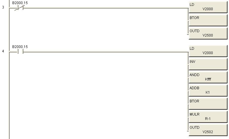
c. Example 2 below uses V2000 as the 2s complement data source and V2500 as our converted REAL value destination.
i. When a 2s complement value is negative, the most significant bit of the word will be turned on. In this example we use the actual most significant bit (B2000.15) to determine if value in V2000 is positive or negative.
ii. If the value in V2000 is positive, we convert to REAL using BTOR directly. (Rung 3)
iii. If the value in V2000 is negative, we invert the bit pattern, ANDD the inverted value with KFFFF, add 1 to it, convert the positive value to REAL using BTOR, multiply by -1 and store the result in V2500.
iv. It is important to note that we did not have to store the positive result in an intermediate address in this example. The result of the INV instructions is a 32 bit word stored to the accumulator. Since, we are only dealing with a 16 bit word, we need to mask (get rid of) the most significant 16 bits. To do this we use the ANDD with a value of KFFFF, which turns on only the bottom 16 bits of a 32 bit pattern.
Click here for 2s complement ladder Example 2.
FAQ ID: 1183
Question:
Can K-Sequence, DirectNet or Non-Sequence be used with the RS-485 ( 2-wire) configuration for port 2?
Answer
Modbus is the only protocol that can be used with RS-485.
DirectNet can be used with RS-422 (4-wire).
K-Sequence and Non Sequence can only be used with RS-232.
FAQ ID: 1185
Question:
What is the SCCR rating for the DL06 PLCs?
Answer
Our PLCs are not power circuit components. The SCCR is not required for them. Please refer to UL508 177.1 and UL508A SB4.1 for details.
UL508 177.1 defines what the PLC is and UL508A SB4.1 covers the standard for the SCCR.
FAQ ID: 1193
Question:
Can I change the backup battery with power applied to my DL06 CPU?
Answer
Yes. Open the battery cover on the top right corner of the unit and insert a new battery.
FAQ ID: 1203
Question:
Do you have wiring diagram for use with the SureStep Drives
Answer
Yes, in the SureStep drive FAQs
http://support.automationdirect.com/faq/showfaq.php?id=1248
FAQ ID: 1251
Question:
What are the color codes for American/Canadian thermocouples?
Answer
All American/Canadian Thermocouples follow the ANSI color standard for wire coloration. Jacket color may sometimes be the main wire color, but it is not a dependable means of thermocouple type.
Type J - White/Red
Type E - Purple/Red
Type K - Yellow/Red
Type T - Brown/Red
Type N - Orange/Red
Red is always Negative.
FAQ ID: 1306
Question:
How do I use a variable as a timer preset?
Answer
In your timer box where you are currently typing 'Kxxx' for the preset you would put a V memory address such as V2000. Make sure that this address is only used for this purpose. Now open a data view and type in V2000. You would use this same V memory address for every timer that you want to have the same value.
Click the yellow E button with the red circle and slash in the upper left of the data view window to enable edits. Now you should have a column titled edits on the right of the V2000 you typed in. Enter your value in this column next to V2000 and press the middle of the three buttons at the top right of the data view.
Please note that you can use other V memory addresses than V2000. The full list of available addresses is available in the PLC -> Memory map menu item. Also you can find the list of available memory in Chapter 3 (or 4 depending on the PLC model) of the User manual.
FAQ ID: 1336
Question:
Does the PRINT instruction support REAL values for the embedded V-memory?
Answer
Yes.
Add ":R" at the end of the embedded V-memory.
An example of a PRINT expression would be
"This is a test: " V2000:R "$N"
If the value in V2000 is 1.234, the result would be:
This is a test:#######1.234
(the # character = one space)
FAQ ID: 1347
Question:
"CTRIO Workbench says my H0-CTRIO2 needs a firmware update" or "I updated the firwmare in my H0-CTRIO2, and now it's stuck in booter mode".
Answer
Older versions of CTRIO Workbench (2.1.x or earlier) will incorrectly identify a CTRIO2 as a CTRIO that needs a firmware update.
Do NOT attempt this. You must get the latest CTRIO Workbench version from HostEng.com (2.2.x or later).CTRIO Workbench
Unzip and install this updated version of Workbench. If you already attempted the firmware update and your CTRIO2 is now stuck in booter mode, you will need to do the same, PLUS, get the latest CTRIO2 Firmware from their website and try to update the CTRIO2 firmware again. You might have to try several times, but if it still won't get out of booter mode, you will need to contact Returns Department.
FAQ ID: 1511
Question:
The D0-DCM module TX1 and TX2 LEDs are flashing simultaneously. What does that mean?
Answer
The D0-DCM flashes both TX LEDs to indicate it is in Firmware Update mode.
You must complete the FW update using the Koyo Support Tool and the Correct FW binary file. Koyo Support Tool and DCM Firmware file
FAQ ID: 1522
Question:
Can I use a reed switch on an AC input?
Answer
We do not recommend this, as the inrush of the AC input can cause the reed switch contact to fail.
Also the reed switch can arc when opening causing a voltage higher than than your system supply.
This higher voltage can quickly damage AC inputs, which have a maximum rating of 132 vac.
Reed switch flutter or bounce can make this condition even worse.
FAQ ID: 1551
Question:
"I can't see my ECOM(100) with NetEdit, or DirectSoft. What do I do?"
Answer
If NetEdit3 doesn't see the ECOM module when you press "Scan Network", check the following:
1) Verify Link Good LEDs are illuminated on module and connecting devices like hubs or unmanaged switches.
2) Turn OFF any WiFi devices or other ethernet devices (Bluetooth may simulate an ethernet connection, turn it off too). Windows moves these devices to the top of the "bindings" list, so DirectSoft tries to connect thru devices at the top of this list.
3) Turn off Windows Firewall ( or any security firewall you may have). The easiest way to find Windows Firewall settings, is to go to Windows Help, and type in "firewall". You will get a link to firewall settings. It's possible if you have an IT department, they will have prevented access to the firewall. You will need to contact them. The ECOM products use port 28,784. Also, turn OFF any antivirus or other protection software that can interfere with ethernet communication.
4) Try to PING the ECOM module to establish basic connection (see Windows Help, or search for resources on internet if not familiar with these steps).
5) You may need to disable any other network adapters besides the one physically connected to the ECOM or network the ECOM is on. If you get "Transport Protocol error", try the instructions in this link:
http://hosteng.com/FAQFiles/ECOM.htm#FAQ0024 Go to Step 4, Item C.
The latest version of NetEdit has the ability to select the specific network adapter, by going to the main Menu, select "Network", then "Adapter" and specifying which installed adapter you want to use ( it also lists the IP addresses of the adapters). We strongly suggest you download the latest version of NetEdit here:
http://hosteng.com/SW-Products/NetEdit3.zip
6) If you have a network administrator, you may need to check with them to verify the configuration of the local network.
7) If you have Windows XP or earlier, and you still can't make a connection, you should consider trying the IPX protocol. Click the IPX button in NetEdit3. If you get the 10047 error, you need to install the NWLink/IPX protocol to your computer ethernet card.
See Windows Help for this procedure, or try this link
http://hosteng.com/FAQFiles/ECOM.htm#FAQ0043
7) If you can't connect to an existing/unknown ECOM100 in a network, and the card is likely newer than 2007, try these steps:
It is possible to clear all the IP settings, returning the unit back to stock values of 0.0.0.0. This will make it visible, BUT, will disconnect any working connections, so use this with care.
DIP #6 performs this function. You would:
Power down
Remove ECOM100
Turn on DIP #6
Re-insert and power up the ECOM100
Scan with NetEdit again, and hopefully it sees the ECOM100. If it does, power down, remove, turn DIP #6 back off again, re-insert and power up.
BE CAUTIOUS, this method will break any existing connections
http://hosteng.com/FAQFiles/ECOM.htm#FAQ0085
FAQ ID: 1574
Question:
How can I make the CTRIO2 output wave form more stable?
Answer
Due to the 10x higher speeds of CTRIO2 modules, the waveform isn't as forgiving as a CTRIO module was.
It might be necessary to use the following circuit if you notice differences between a CTRIO and CTRIO2 module being used as a replacement.
R: 10 to 50 ohms, C: 22nF (0.022uF)
Connect the R & C in series, then connect that across the CTRIO2 outputs (preferably at the stepper's inputs instead of just right at the CTRIO2's outputs).
FAQ ID: 1595